
Oxidative Stress Detector replication guide

Oxidative Stress : This instructable guides you through creating an oxidative stress detector designed to measure electro-ionic flow, an indicator of oxidative stress in the body, on the nanoAmp scale. The oxidative stress detector uses a probe connected to a CurrentRanger, a commercially available nanoAmp current meter. These detailed instructions specifically outline how to build an oxidative stress detector with specialized circuitry to measure ultra-low amperage currents. In addition to the probe itself, the detector includes additional features such as WiFi data linking, cloud datalogging, an OLED display, and a portable case.
Oxidative stress is a factor in inflammation. Leveraging electron donation technology, the oxidative stress detector pinpoints ideal spots for anti-oxidative patches, such as Heliopatch. Creating an electrical circuit, electrons flow from the magnesium disc through the nanoAmp reader, probe, and into the body. Concurrently, the user's thumb interacts with the ionic bridge button, essential for ion exchange and circuit completion. The detector identifies areas with high oxidative stress or conductivity.
According to Oval.bio research, regions near oxidative stress attract electrons due to a concentration of free radicals. These positively charged radicals, seeking an electron pair, generate an electron flow detected as nanoAmp electrical current. Moving the probe towards oxidative stress enhances electron transfer, detected by the probe. This non-invasive method aids in locating areas of oxidative stress for optimized relief. Holding the detector supports electron donation, yet the primary therapeutic advantage lies in Heliopatch when applied to the identified skin region. Utilizing the same electron donation technology, the patch alleviates oxidative stress effects by neutralizing hydroxyl radicals from magnesium ions.

In addition to oxidative stress, nanoAmp-measured electro-ionic flow correlates positively with body surface conductivity. Conductivity refers to the body's surface ability to facilitate electron flow from an external source to internal free radicals. Identifying areas of high conductivity is valuable, allowing the most electrons to flow from Heliopatch into the body.
While Heliopatch is akin to the probe, using it alone has drawbacks, notably the inability to quantify electron donation to the body. Unlike the oxidative stress detector, the patch can't pinpoint the location or measure electron donation. The patch's immobility makes optimal placement challenging, unlike the probe, which addresses this issue. Using both the probe and patch together yields optimal results; the probe guides the patch placement.
The open-source, patent-pending design from old.revamp.oval.bio aims to build life extension pods using electron donation technology. Early prototypes involved tentacle-like rubber probes or a bed of soft needles to detect oxidative stress locations on the body. While these designs lacked user comfort, they inspired the handheld oxidative stress detector as a practical solution.
The oxidative stress detector uses Arduino software, specifically the IDE. To download the Arduino IDE, please refer to this link.
Bill of Materials (Unit costs revised August 2020)
CurrentRanger $120.00
OLED LCD Screen $27.99
WiFi Development Board $12.99
Lead Wire $25.59
Female Post Banana Plugs (4 pcs, 4 mm) $9.99
Male FosPower Banana Plugs (4 pcs, 4 mm) $8.99
IC Breakout Board $3.00
8-Pin DIP IC Socket $1.50
10 Pin Header $0.69
18650 LiPo battery $11.59
Attiny13 MicroProcessor 1.8-5.5 V $0.82
Mini Push Button Switch $5.89
12” x 12” Acrylic Sheet* $16.95
0.5 x 20 mm Hex Screws (2) $1.40
TOTAL $264.17
Additionally, you'll need basic workbench tools, solid core wires, Dupont wire housing, soldering materials, and your 3D printer software/filament to complete this project.
*Home Depot, Lowe’s and other specialty hardware stores can cut this to the appropriate size if you do not have the appropriate tools
Step 1: CurrentRanger and OLED Screen
Section 1A:
First start with a blank CurrentRanger Board as shown below (Figure 1A.1).
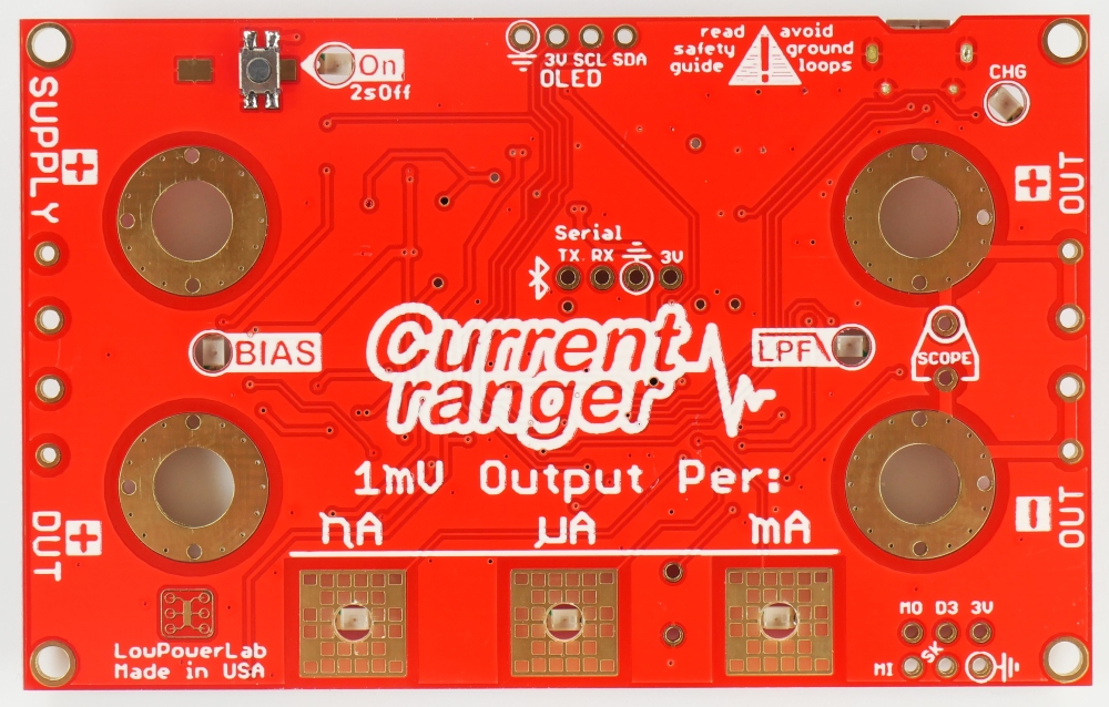
Figure 1A.1 (Courtesy of
)
Next, place and solder two 4 by 1 Dupont Jumper Wire Housings on the OLED and Serial Pin locations on the CurrentRanger Board (Figure 1A.2). Solder these pins in prongs-down (relative to the top of the board).

Figure 1A.2
Before the CurrentRanger can download anything, install some code and libraries. Begin by installing the Current Ranger board support package, which is available as a downloadable IDE file. To do this, go to “Arduino” > “Preferences” and in the text box labeled “Additional Board Manager URLs”, copy and paste this link: https://lowpowerlab.github.io/MoteinoCore/package_LowPowerLab_index.json. Close out of the Arduino IDE. Then reopen the IDE and go to “Tools” > “Board” > “Board Manager”. Search “Ranger” in the search bar and install the LowPowerLab Board Manager.
The zip files of several libraries also need to be installed including libraries for emulating the EEPROM, the touch control pads, and the display driver. Once these zip files are downloaded, go to “Sketch” > “Include Library” > “Add .ZIP Library” and add each of the three libraries.
To ensure that the board is functioning properly, we will run one of three sketches that will be eventually downloaded onto the CurrentRanger. Assuming you already have the Arduino IDE installed, download the cr_bt_force.inosketch from the old.revamp.oval.bio GitHub repository or download the file from the open source Google Drive folder.
In Arduino IDE, after importing the code, ensure the correct board support is installed. Navigate to "Tools" > "Board: [some name]" from the menu bar and select "Boards Manager" (Figure 1A.3). Search for "samd" in the manager, and choose "Arduino SAMD boards." If SAMD screen support isn't enabled, click "Install" (Figure 1A.4) for the latest version. For an existing installation, click "Update" (Figure 1A.5). The window confirms if the package is installed and fully updated (Figure 1A.6). With the package installed and updated, the proper board support is ready.

Figure 1A.3

Figure 1A.4
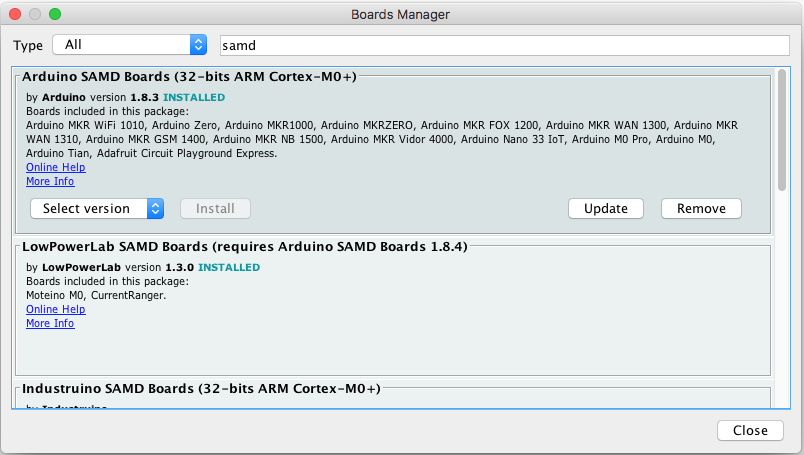
Figure 1A.5

Figure 1A.6
Additionally, ensure the correct boards and ports are selected. Make sure the micro USB cable is connected to the CurrentRanger and the computer (Figure 1A.7). Then, from the menu bar, go to “Tools” > “Boards,” and select “CurrentRanger” (Figure 1A.8). Then, also from “Tools” in the menu bar, go “Port” and ensure that an “CurrentRanger” is selected (Figure 1A.9).
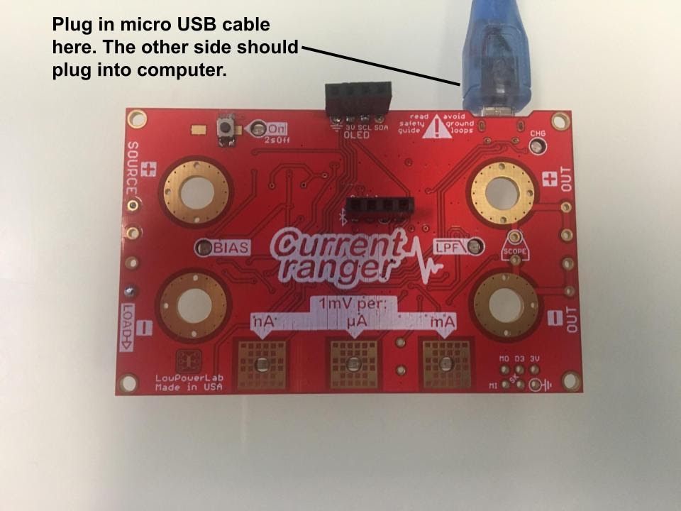
Figure 1A.7
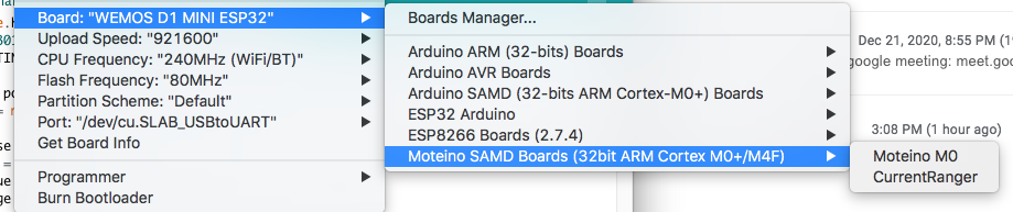
Figure 1A.8
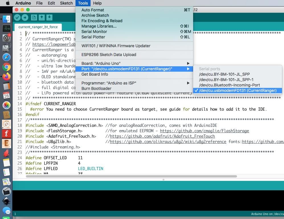
Figure 1A.9
To upload the program onto the Arduino, navigate to the menu bar, and go to “Sketch” > “Upload” (Figure 1A.10). Make sure to double check the settings and upload the code each time the sketch is updated.
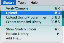
Figure 1A.10
If the following steps were downloaded correctly, turn on the board by hitting the power button (Figure 1A.11) and the board should light up as shown (Figure 1A.12).
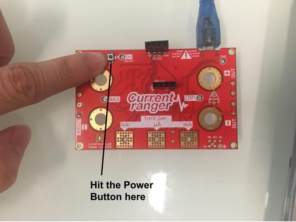
Figure 1A.11

Figure 1A.12
Additionally, with the Serial Monitor in the Arduino IDE pulled up, there should be several readings being read from the CurrentRanger. On the nanoamp scale, these values should be fluctuating a bit as well and be greater than 0. If the serial monitor is not displaying correct values, ensure the speed is set at the correct baud: 115200 baud (Figure 1A.13).
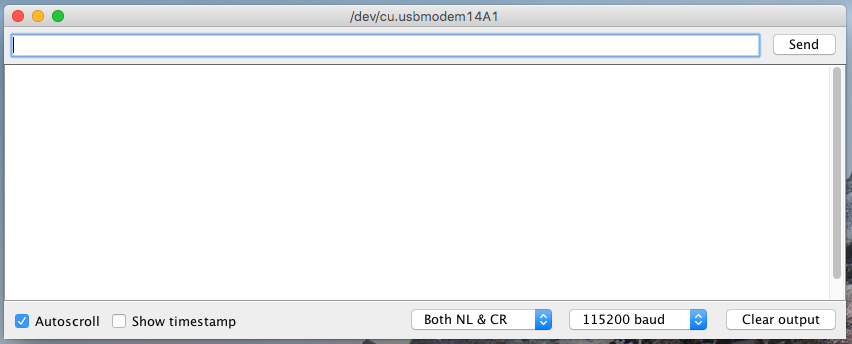
Figure 1A.13
In the previous section, for an additional check, connect a four-prong OLED screen to the CurrentRanger’s OLED socket. Verify the OLED screen displays values matching the Serial Monitor, keeping in mind that the OLED screen rounds values to the nearest tenth while the Serial Monitor rounds to the nearest whole number. After testing, disconnect the OLED screen.
Whenever removing the CurrentRanger from the computer, turn it off by holding the power button until the lights go off. Unplug the CurrentRanger from the computer. This step is essential for all subsequent instructions where the CurrentRanger is connected to the computer.
Section 1B:
Set the board to the side. We will now work on the OLED display for the oxidative stress detector.
First we will need to connect the ATTiny microprocessor so it can be programmed. Connect the ATtiny with your Arduino such that it looks like the schematic below (Figure 1B.1)-- the pins on the Arduino correspond to the pins on the ATtiny.
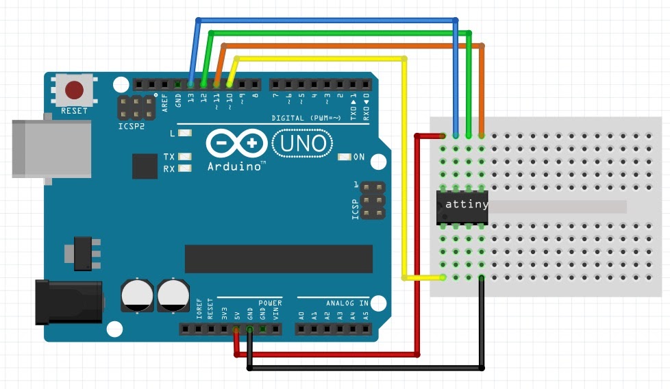
Figure 1B.1
Next, install board support for the ATtiny, which can be found here. This support is needed so that the ATtiny is treated as an Arduino. Then, upload an example sketch onto the Arduino Uno. This file can be found in the Arduino IDE by going to “File” > “Examples” > “11.ArduinoISP” (Figure 1B.2). Then, ensure that the ATTiny board manager, which can be found here, is loaded. Download the oled_init_attiny13.inosketch from the old.revamp.oval.bio GitHub repository or download the file from the open source Google Drive folder.

Figure 1B.2
After connecting the Arduino to your computer, ensure the following settings are configured before uploading the sketch. Under the 'Tools' menu, set the board to 'ATtiny 13,' disable BOD, choose a 1.2 MHz internal oscillator clock, and select 'Arduino Uno' as the port (Figure 1B.3). Then, click 'Burn Bootloader' in the 'Tools' menu. Once completed, choose 'Sketch' > 'Upload Using Programmer' (Figure 1B.4). After programming the ATtiny, unplug the Uno from the computer and disconnect the ATtiny processor from the programming breadboard.
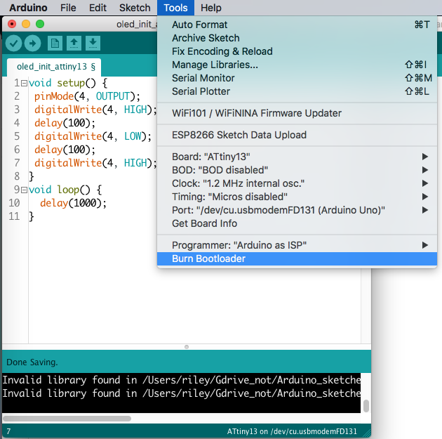
Figure 1B.3
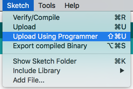
Figure 1B.4
Next, remove one corner pin from the 10-pin header. Use a blank breadboard to assemble the schematic below with a 10-ohm resistor (as specified in the BOM), a nine-pin header, and a chip (Figure 1B.5). Take note of the two rows on the schematic labeled 'Row 1' and 'Row 2' for future steps. Bend the header pins 90 degrees, placing the open ends of the housing above the board's edge (Figure 1B.6). Optionally, a dip socket can be used to attach the chip to the board, as shown in the picture.
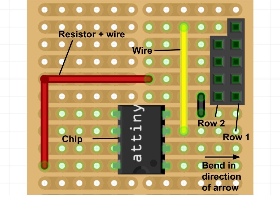
Figure 1B.5

Figure 1B.6
Plug in five Dupont jumper wires (which consist of housing and wires) into Row 1-- the row with five header pin holes-- on the breadboard (Figure 1B.7). Schematic, Figure 1B.5, illustrates Row 1.

Figure 1B.7
Plug in four Dupont jumper wires into Row 2-- the row with four header pin holes-- on the breadboard (Figure 1B.8). Schematic, Figure 1B.5, displays Row 2.
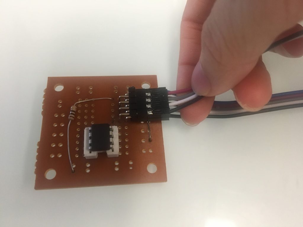
Figure 1B.8
Set the breadboard aside. On the back of the OLED screen, remove resistor R4 and replace it with jumpers R3 and R5 using a solder bridge (or a low-value resistor). Solder five header pins into the GND through RES holes. Connect DC and CS to GND using solder and a resistor (or jumper wire). Turn the header pins 90 degrees, facing the nearest edge of the OLED display, as illustrated below (Figure 1B.9).
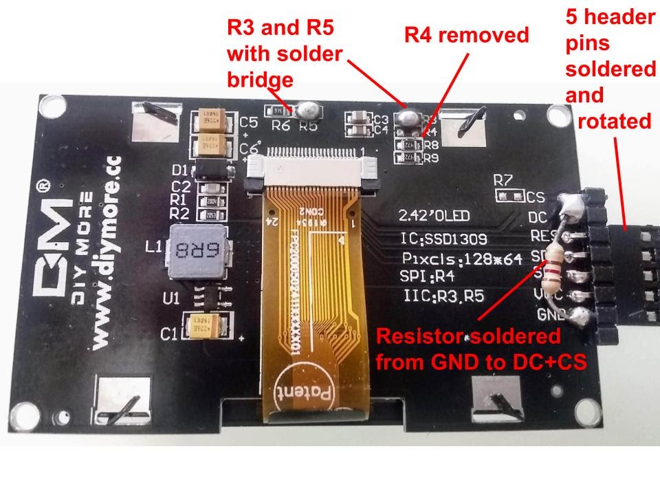
Figure 1B.9
Taking the breadboard and wires, connect Row 1 (as labeled in Figure 1B.5) to their associated pins on the OLED display (Figure 1B.10). Confirm the correct wires are connected in a 'one-to-one' fashion (i.e., connect the ground wire to the ground pin). A helpful illustration is provided below (Figure 1B.11).
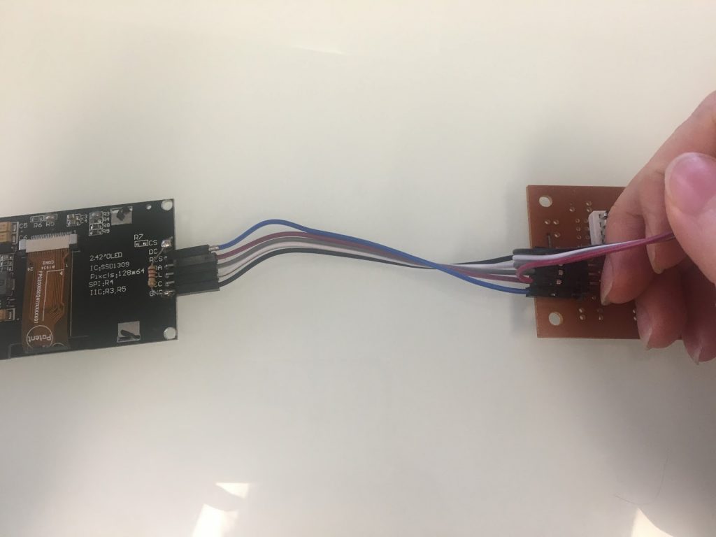
Figure 1B.10
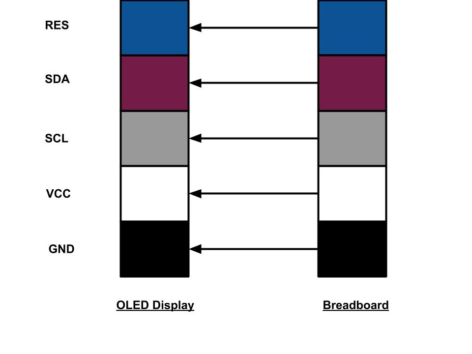
Figure 1B.11
Next, plug in the wiring from Row 2 on the breadboard (as labeled in Figure 1B.5) to their associated pins on the CurrentRanger, on the four holes near the top of the board labeled “OLED” (Figure 1B.12). Once again, confirm that the correct wires are connected in a 'one-to-one' fashion (i.e., connect the ground wire to the ground pin). A helpful illustration is provided below (Figure 1B.13).

Figure 1B.12
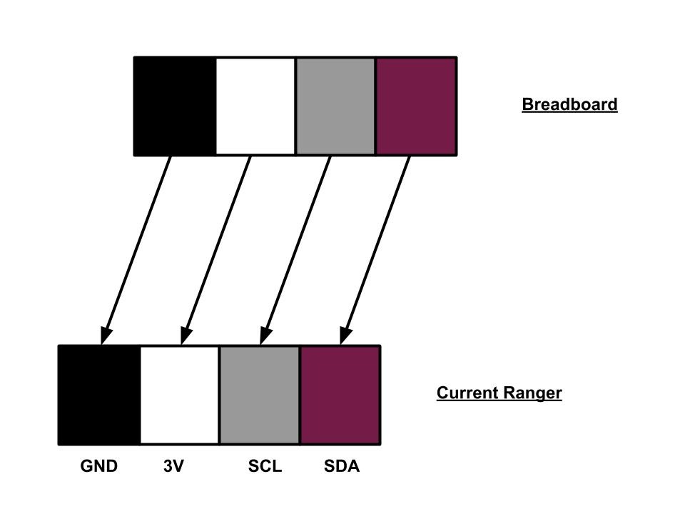
Figure 1B.13
Double-check the OLED screen's connection. Make sure to download and update the SAMD board manager (refer to Figure 1A.3 through Figure 1A.6). Once properly connected, power on the CurrentRanger. The OLED display should activate, showing changing readings similar to Figure 1B.14. Confirm correct installation, then turn off the CurrentRanger by holding the power button and unplugging the micro USB.

Figure 1B.14
Section 1C:
Cut two solid core wires, approximately 6 inches in length (preferably of two different colors to make it easier to distinguish in later steps). Figure 1C.1 shows one such wire. Remove the insulation from the ends of both of these wires-- about an eighth to a quarter of an inch in length on both sides.

Figure 1C.1
Next, solder the two wires into the CurrentRanger. Solder one end of one wire into the 'SOURCE (+)' hole and the other into the 'LOAD (-)' hole on the left side of the board as shown in Figures 1C.2 and 1C.3.

Figure 1C.2
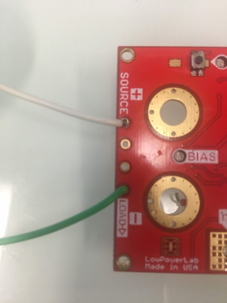
Figure 1C.3
Next, take two Dupont jumper wires(Figure 1C.4), which should be approximately 6-8 inches in length.

Figure 1C.4
Bend the one end of each wire at about a 45 degree angle (Figure 1C.5).

Figure 1C.5
Solder one end of one of these wires to one of the solder pads next to the on-off switch of the CurrentRanger. Solder the other wire to the solder pad diagonally opposite from the previous wire (Figures 1C.6 and 1C.7). Ensure there is sufficient solder such that the wire stays in contact with the solder pad, but not too much such that the solder comes into contact with any adjacent solder pads.
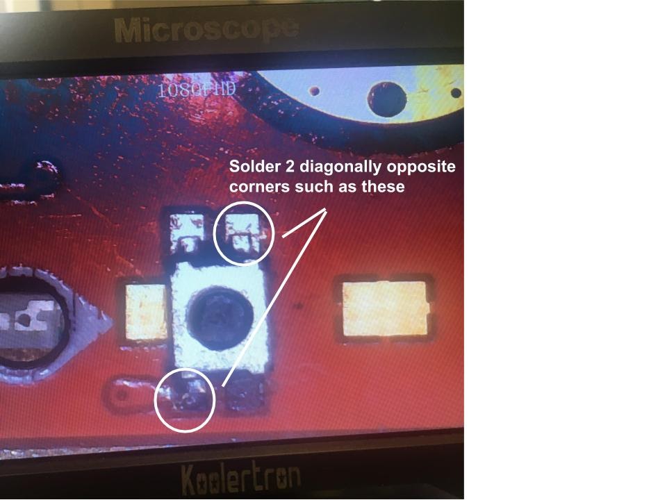
Figure 1C.6
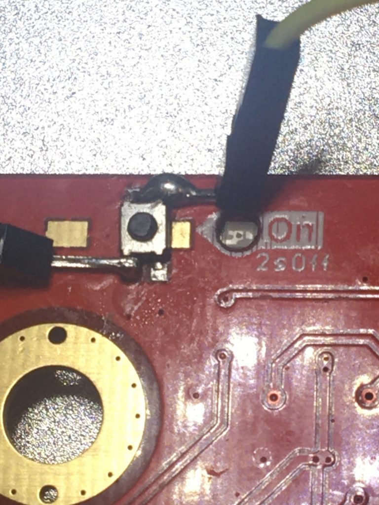
Figure 1C.7
To test the soldering done in the previous step, plug in the CurrentRanger into a computer via the micro USB. Touch the exposed housing of the two newly attached wires. The OLED screen should turn on after a couple of seconds (Figure 1C.8). If it does not turn on, reattach the previous two wires with Dupont housing. Turn off the OLED by holding the wires together a second time.
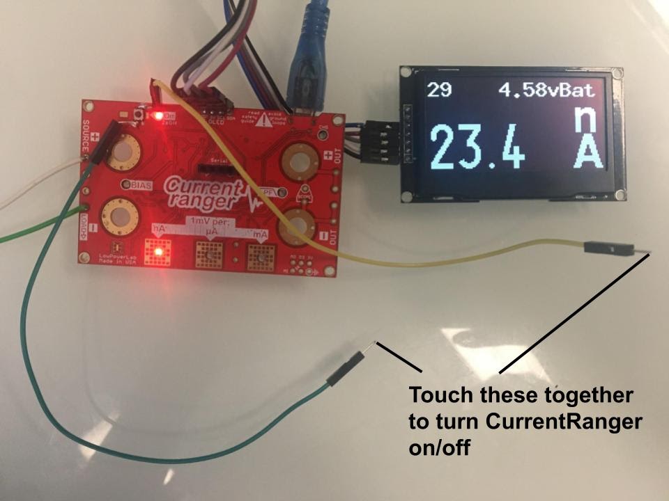
Figure 1C.8
Step 2: Probe Construction
Section 2A:
Cut two pieces of the lead wire-- each approximately 5 feet in length. Figure 2A.1 shows one such wire.

Figure 2A.1
Take off approximately a half inch of insulator on both sides of each wire. Pinch and twist the exposed copper wire on all of these ends. Figure 2A.2 illustrates an example of one such end.

Figure 2A.2
For each wire, attach a banana plug and its outer sleeve on one end. While all four plugs are identical, it's advisable to use plugs of the same 'color' for one wire, determined by the FOSPOWER logo on the outer sleeve (two reds and two blacks). Simply attach a red banana plug to one wire and a black one to the other (Figure 2A.3). Refer to Figure 2A.4 for instructions on inserting the banana plugs.

Figure 2A.3

Figure 2A.4 (Courtesy of
)
Next, print the casings for the respective plugs, which are the files anode_plug.stl, anode_holder.stl, inner_sleeve.stl, and outer_sleeve.stl. These files are all found in the open source Google Drive folder.
After printing the parts, slide the anode cap and anode plug onto the black (negative) banana plugs (Figure 2A.5), and attach the inner and outer sleeves to the red (positive) banana plugs (Figure 2A.6). The final product should look something like Figure 2A.7)

Figure 2A.5

Figure 2A.6

Figure 2A.7
Section 2B:
Print the part endcap1b.stl (not to be confused with endcap1.stl), which can be found in the open source Google Drive folder.
Mount the power button onto the endcap1b print and the USB extension. Install all the jacks onto the endcap1b print. Solder the positive (red) wire onto the plug with the red banana jack and the negative (black) onto the black banana jack. Solder the power wire onto the power button. Take the micro USB to USB A adapter plug and insert it into the USB extension, then use two 3 mm screws to secure the USB adapter (Figures 2B.1 and 2B.2).

Figure 2B.1

Figure 2B.2
Section 2C:
Set the CurrentRanger and OLED display to the side, we will now work on the wifi development board for the oxidative stress detector.
Take the blank wifi module as shown below (Figure 2C.1).
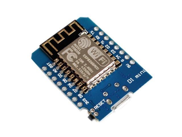
Figure 2C.1 (Courtesy of
)
Before installing the WiFi Module, you need to install another board manager, specifically the NodeMCU Support File. To download this, go to “Arduino” > “Preferences” and in the text box labeled “Additional Board Manager URLs”, copy and paste this link: http://arduino.esp8266.com/stable/package_esp8266com_index.json . Close out of the Arduino IDE. Then reopen the IDE and go to “Tools” > “Board” > “Board Manager”. Search for 'esp8266' in the search bar and install the displayed board manager. Download this file by connecting the WiFi module to the computer.
Then, go to “Tools” > “Port” and select the option that says “cu.wchusbserial” (Figure 2C.2). Next, adjust the board settings such that the board is “LOLIN(WEMOS) D1 R2 & mini”, the upload speed is 115200, the CPU frequency is 160 MHz (Figure 2C.3). Make sure that the rest of the board settings match the rest of the settings shown on Figure 2C.3 as well. Then download the meter_telemetry.inosketch from the old.revamp.oval.bio GitHub repository or download the file from the open source Google Drive folder. Then, upload this sketch to the WiFi module by going to Sketch” > “Upload” (Figure 1A.10).
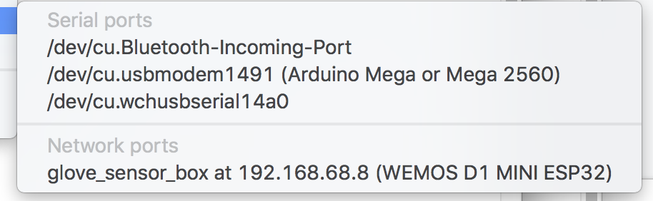
Figure 2C.2

Figure 2C.3
Next, solder 3 pin male cables to board on these holes: 3V3 RX GND (Figure 2C.4). Then, connect these wires (the ESP board RX connects to the Current Ranger TX) to the CurrentRanger’s serial wifi boards (Figure 2C.5 and 2C.6)
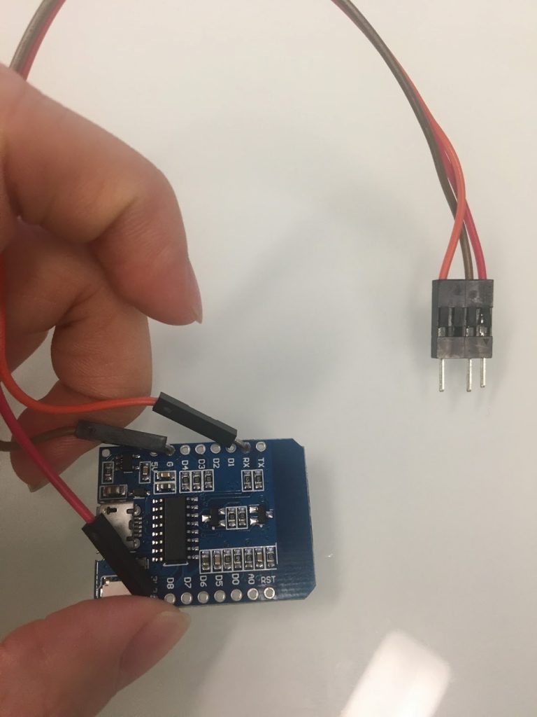
Figure 2C.4

Figure 2C.5
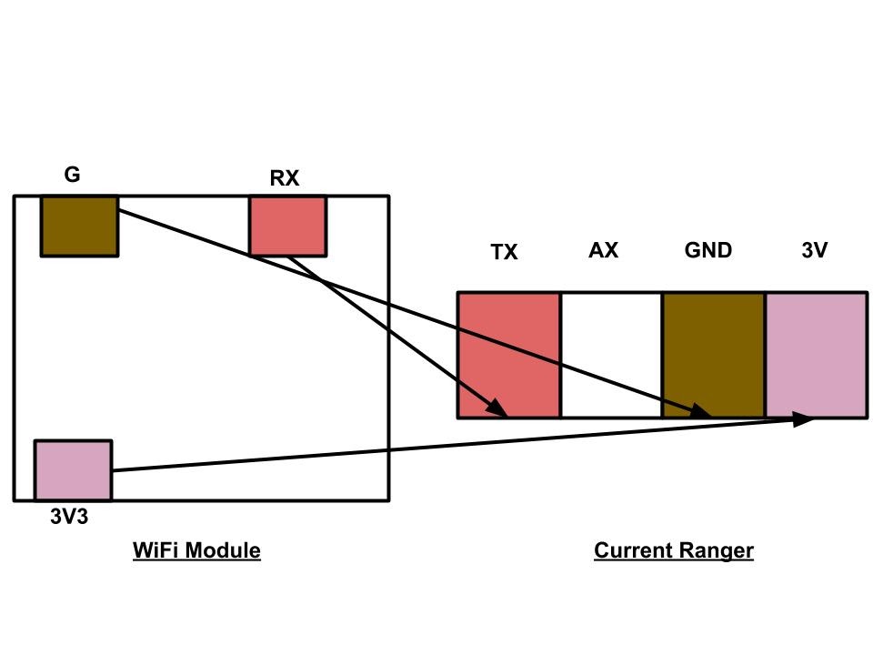
Figure 2C.6
Step 3: Box Construction
Section 3A:
Print the file called LCD_holder.stl which can be found on the open source Google Drive folder. Using a total of 10 zip ties, zip tie the hardware to the holder-- use 1 for the adapter, 2 for the Current Ranger (through the large holes), 4 for the LED screen (one on each corner), 2 for the battery, 1 for the WiFi module. (Figures 3A.1 and 3A.2)

Figure 3A.1 (back view)

Figure 3A.2 (front view)
Attaching numerous zip ties can be a bit confusing, so here are some tips to simplify the process:
The LED screen is on the top of all the other pieces of hardware, and it should align with where there are notches-- it should also align with and wires come from side
Attach one corner of the LED screen to the development board.
Underneath the Current Ranger, there should be two wires which go around the board
The adapter wraps around the box, and zip ties secure the wifi module and battery to the adapter cable.
Zip tie everything first, then add the add WiFi module, then add zip tie onto wifi module
Insert the WiFi module with the USB facing outward to avoid removal in case of reprogramming.
Finally print the parts endcap1.stl and side_panel.stl (the latter of which needs to be printed twice). These parts can be found in the open source Google Drive folder. In addition, cut a piece of acrylic (or order it) in the size 100 mm by 150 mm.
Assemble the endcap1b piece, along with the acrylic and two side panels (Figure 3A.3).

Figure 3A.3
Then, slide the LCD panel and all the zip tied hardware into place (Figures 3A.4 and 3A.5).

Figure 3A.4

Figure 3A.5
Finally, close the box with the endcap1 piece. Secure with four 3 mm screws to lock everything in place (Figures 3A.6 and 3A.7). This is your final product.

Figure 3A.6

Figure 3A.7